
Project overview
In this design problem you had to use your knowledge of synchronous counters to design a 60 second timer that would count to 59 and reset with a reset button.
PLd circuit
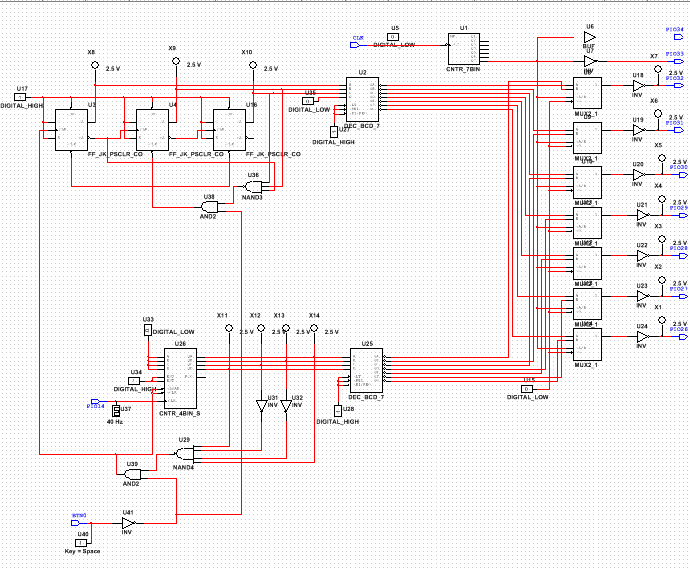
this project it is very similar to the dmv display because it counts up to a number but Unlike the DMV counter this project didn't stop at its limit, instead it resets back to 0 and continues to count. This also counted from 0-60 instead of 0-80. It also uses j/k flip flops and a synchronous 163 MSI counter.
Final Project conclusions
1)Synchronous Circuits are sequential circuits that are governed by a clock. , synchronous clock signals are less susceptible to circuit anomalies which make them safer to operate. But they lack speed from the delay of the clock signal. Asynchronous circuits operations are instantaneous since they dont have to wait for a clock pulse. They are affected delay of logic gates only. asynchronous circuits suffers from the ripple effect.
2) A '163 chip displays the number it detects and the downside of the chip is that it can only count up. also it has a synchronous load and clear. A '193 chip displays one number before the number it detects. The upside of this chip is that it can count up or down. also it has asynchronous loads and clears.
3) First i placed down 3 jk flip flop gates i connected not q to clk then i placed down 3 probes and connected q to them. i then placed down a digital high and connected all the presets to it including all the j and ks. then i connected ABC from the decoder to the probes in order A went to probe one b to probe 2 and c to probe 3. D is connected to a digital low. after this was wired up i added a 3 prong nand gate and connected the first prong to c the second prong to the not q and clk then the third prong to b. not clks on the flip flop were wired to the single [point of the and gate the back side was connected to the reset button and the 3 prong nand gate. Now i needed to create the counter that counted to 9. i used a 163 chip and wired not abcd to a 4 prong nand gate i then placed inverters on not b and c so that it would detect a 9. i connected pin 14 to clk and digital high to end and ent. i had to make sure that it started a 0 so i placed a digital low and connected abcd. i took the front prong of the 4 prong nand gate and connected it to the and gate. i took the other prong of the and gate and connected it to the reset button which was a digital interactive with an inverter. finally i connected the clk of the first jk flip flop and wired it to the clk and load of the 163. also connecting it to the first prong of the and gate.
4) many kids and i have a similar design but the main thing that i saw that was different was the inverter on the reset button i have no idea why some needed inverters and others did not.
