
Project overview
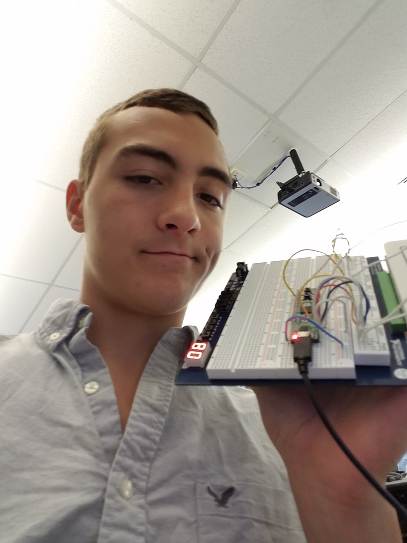
In this project, we created an asynchronous up counter that counts from 0 to 80 and then stops. After that we had to add in a reset switch, that will reset the count to 0. The counter itself is controlled by a clock that is connected through multiple flip-flops. After we had built this in Design mode on MultiSim, i had to re-build it in PLD mode, and then upload it to a chip to be able to test it on a photoboard.
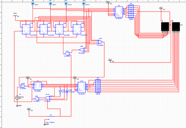
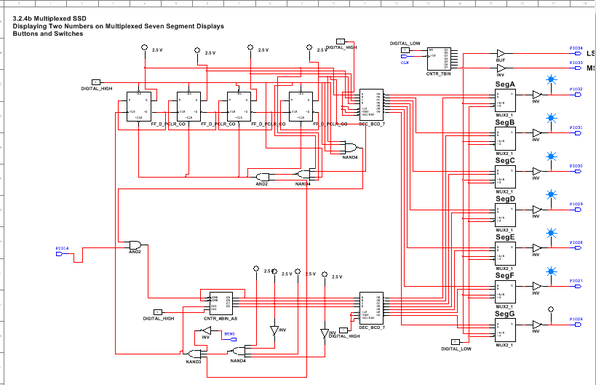
The first design i created was in design mode on MultiSim, after i had successfully crated the project i made it in In PLD mode. All the parts are the same except the names are different. also you have to assign pins for inputs and outputs. The number of the pin matches to the pin on the chip. with PIO14. You will wire a button to that pin. the output looks the same as the input, except the wire goes out to the left. In order to upload the circuit on to the chip you need The specific folder. When you have built the circuit, you need to hit Transfer, then Export to PLD. Next uncheck the save button then change it to 64-bit. make sure that the user constraint files are selected to Diligent C-Mod, and then click Finish.
Bill of materials
Bread board 2.0 = 1
power box = 1
C -Mod s6 chip = 1
wires = 14
power box = 1
C -Mod s6 chip = 1
wires = 14
Finial project conclusions
After this project i now understand asynchronous counters and how they work. The difference between SSI and MSI circuit. SSI stands for Small Scale Integration, and MSI is Medium Scale Integration. An ssi has less than 100 components about 10 gates. An msi contains less than 500 components and less than 100 gates. MSI gates save space but have downside an MSI gate can only start start at 0. asynchronous counters are not in sync with the clock. asynchronous counters have delays between certain parts and the clock, causing a ripple in the graph. This is known as the ripple effect, and will most likely occur in every asynchronous counter that is powered by a clock. My ones display was made up of a MSI asynchronous counter (74LS93) and was hooked up to a COMMON anode display, using inverters and NAND gates to detect a 10 on the scale, but reset to 0 once you see the number 9. Many of my class mates had different designs they were a lot simpler for some reason i over thought it and made a very difficult design.
