
Project overview
This project you will use only AND, or and or inverter logic gates to design, simulate and build a majority vote voting machine that meets these design specifications.
Truth table
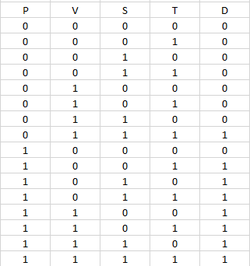
This truth table shows all possible outcomes in the project. P stands for President, V for Vice President, S for Secretary, and T for Treasurer. For each row the value of the row increases. for example it goes from 0 to 1 to 2 to 3 and so on. the decision will pass if the president i voted on it .
The unsimlified logic is 'PVST+PV'S'T+PV'ST'+PV'ST+PVS'T'+PVS'T+PVST'+PVST. This expression is SOP. Each midterm comes from the 1 in the decision column of the truth table.
The unsimlified logic is 'PVST+PV'S'T+PV'ST'+PV'ST+PVS'T'+PVS'T+PVST'+PVST. This expression is SOP. Each midterm comes from the 1 in the decision column of the truth table.
unSimplified curcuit
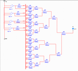
This is the unsimplied circuit for the logic expression. It utilizes a bus connecting all the inputs to the outputs with ease, making it easier to create and cleaning up the circuit making it neater this circuit uses 24 AND gates and 7 OR gates. That would require 6 74LS08 IC chips and 2 74LS32 IC chips
boolean algebra
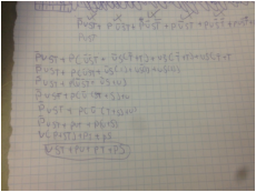
Boolean algebra is A division of mathematics which deals with operations on logical values. i used Boolean algebra to simplify the long expression so i could create the simplified circuit the simplified logic expression is vst+pv+pt+ps=D
simplified curcuit
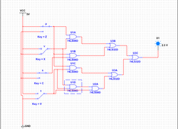
This is the simplified circuit i made this with the simplified logic expression. I decided to not use Bus form because i though that it would be easier to bread board looking at this. to construct this it requires fewer gates, only 5 AND gates and 3 OR gates . The circuit now only needs 2 74LS08 IC chips and 1 74LS32 IC chip. This circuit is a lot better than the unsimplified circuit. It uses fewer gates and requires fewer chips.
Bread-boarding
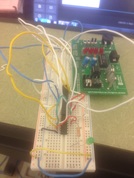
this shows the entire bread board with the 3 ic circuits and the bread board component
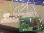
S1 represents P, S2 represents V, S3 represents S, and S4 represents T.
the power source is grounded and powered. S1 has to be connected to the other side of the circuit with a wire so I can use S1 more times.
While bread-boarding at first it was difficult i honestly had no idea what i was doing i had to ask for help from the best teacher ever and she gave me a packet. this packet had the layout of the the ic ships so i would know how to wire them and what gates went where. i was almost done until the bell rang on Friday and i had to leave and start again on Monday. When i came back i forgot where i left off and this caused me to make many mistakes. after about ten minutes i remember where i had left off and finished my circuit. the problem was that i forgot to bridge all my connections. once they were all bridge the circuit worked great.
material list
To bread board i use
- 30 wires
- 2 74LS08 IC Chip
- 1 74LS32 IC Chip
- 1 LED
- 1 resistor
conclusion
this project has help me to understand how to bread board and read ic chips. Im sad to say that i cant take much away from this because i cant see my self working with this stuff in the future, but this has tough me that things that seem difficult may not be. also This project was very informational on how to construct a circuit with a problem statement. i first stared by reading the problem statement. From there i created a truth table. the truth table gave me an unsimplified logic expression. With is logic expression created an unsimplified circuit. after i created the circuit had to simplify the logic expression with Boolean algebra.The Boolean algebra was very hard to do, but i eventually got it. Without the Boolean algebra i wouldn't of been able to build it on the bread board with in the time i did. it would of taken me hours that's why Boolean algebra is so helpful and im glad i know how to do it. Then i created the simplified circuit, from there i then made it on the breadboard. In addition i wouldn't mind doing something like this again in the future.
